 |
DIY • Do it Yourself • Weekend Projects • BIG Projects • LITTLE Projects | |||||
|
DIY • Do it Yourself • Weekend Projects • BIG Projects • LITTLE Projects | |||||
How Do I Share My How-To?It's really pretty easy, pictures and videos of the steps it takes to complete your project are stored on YouTube and picasaWeb. Once your "final" video is stored on YouTube, your project will show in the listings on the site. All this is controlled by our Creator's Tools. Basically, you start a project by writing up the project idea. Step 1. Sign up for a free Creator's Account to gain access to the Creator's Tools. Step 2. Login Step 3. Push the "Create New Project" button on the Creator's Tools. Make a name (you can change it later) for your project. And describe your plans to use as notes to guide the creation of the steps. Step 4. When you've finished providing all the steps to your project, shooting the videos and saving to google video via the Creator's Tool Panel, you are ready to write the introductory paragraph with an interesting story of how you did it, or how you do it in the case of a professional services presentation. Step 5. Last but not least create and upload the video (to YouTube) which is the video that will be used to summarize the project. If you were building a robot, this final video would show the robot running around, doing fun things that will inspire others to create their version of your project. That's it... Watch the views and ratings for your project pile up along with the sales commissions! Or get a customer because you showed how you remodel a house. |
FAQ About Becoming A CreatorQ. Why would I go to all that work, building something, then put it on a website like C What I Can Do? What's the point? A. Actually, there are a couple of forms for a reward:
|
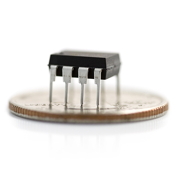
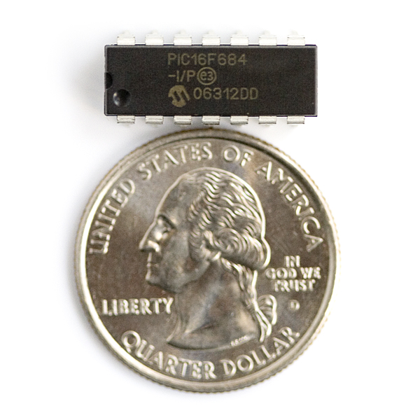
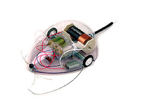
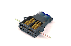
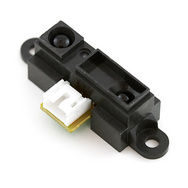
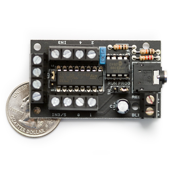
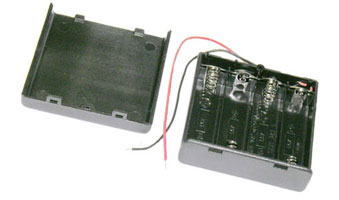
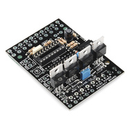
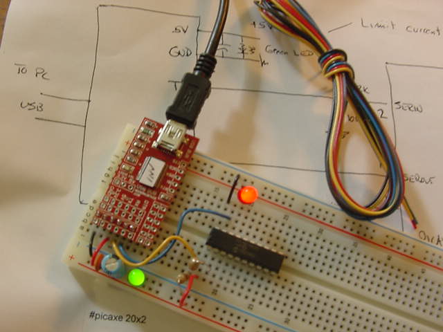
Pong))))) ... 32012 Views Author's name: weRbots The mighty Ping))) ruled the earth until along came the super-empowered Pong))))) !!!!!!!!!!!! Pong The 12volt alternative for robotics work hugely shockproofed. Also using pvc pipe as Robot Body... In this project, I`m sharing my `ordeals` with the ultrasonic transducers for `outdoor` or `rugged` applications. In my robot hobbying around what it means is that if you use ultrasonic sensors in your hobby robot that is destined to crash into things, get stuck, fall off tables, decks, anything in the normal world `out there`. The ultrasonic transducers here are gonna come to hobby roboticists. Somebody is going to do all the grunt work to make a product, then sell it to us at an affordable price. Everyone can see the deets on my experience, anyone better qualified can see the mistakes I`m making and can jump right on this very website and show us hobbyists how it`s done. Or anyone (Parallax - Are you hearing us?) who can bring us the benefits of the Mighty Pong, is welcome to do so. PLEASE PLEASE PLEASE We want affordable sensors. Be realistic, they need to tell other sensors (since any bot is going to need to use multiple units.) They are `using` the airspace, so you can have two or more units pointing into the same airspace without leaving the others in the dark. This means a Jumper that makes it `slave` to the Master so the slaves can also simply `listen` while their shared-airspace siblings blast out a pulse. Like this: Center Pong Fires, L and R listen. I poll all three and their relationship to the center gives potentially valuable information to the navigation control system. Scenario 1. L and R hear nothing. I have an object in the center field. Scenario 2. L hears a signal and so does R, BIG Object ahead - steer or stop... A. Check strongest (L / R) decide which way to check Not Center, Not toward Strongest (L/R). Scenario 3. No return to C, but when L fires, C and R listen, C hears return, L nothing. React appropriately to the large object on your Right. You get the picture... BTW, this process needs to constantly run at a speed appropriate to the mass of your robot and ability to stop within a safe distance of what could be a human, animal, who knows, it`s dynamically entering the zone where my robot has to protect me. I`ve been hit by my own robot a number of times, so I`m telling you, this is an issue for us. The hobby robot has the same issue, it`s looking for obstacles, only the mass has changed, and we probably have a plastic chassis, not a welded body. For this guy, he wants cheap, but he want RUGGED!!!! I wish I had a dollar back for every $10 spent on rangers, both optical, and ultrasonic. I could build a new bot!!!! Testing the Outdoor Super Powerful Ultrasonic Transducer First out of the gate - Test these new ultrasonic transmitters and receivers. They are built for automotive (outdoor) use. They need some fancier than the competitor trickery but should be awesome. Here`s the Test Setup with the complete chain. You are seeing the transmit unit being driven by a very large (over 150vpp) signal to stir up the powerful transmit side of the transducer. The receiver is the same type ultrasonic transducer, located a little less than an inch away from the transmitting unit. The scope shows a signal that`s almost 0.5vpp! That`s a whopping signal, image the suggested 300X amplifier... You could be 300 inches away and still get a large signal. So the Pong))))) could, according to this proof of concept, get a strong signal at least 150 inches away (signal will be bounced back) that`s over five feet. In practical applications, it won`t do that well, but your probably gonna get 3ft of range. That will be proved or disproved in subsequent testing and tuning. Oh, one more thing, this thing likes 41.7kHz, not 40.0, though it is spec`d +- 1kHz. The Tool Chain Furthest to nearest. 1. A 30-60kHz signal generator using a picAxe 08M chip. 2. A seven watt audio amplifier, this is an off the shelf one I had laying around. I suspect you can better this with ease. 3. A 1K to 8 Ohm transistor ampifier transformer, with the amp feeding the 8 ohm side and the transformer providing over 100v to drive things. 4. An ultrasonic transducer. This one is the parallax unit built for outdoor use. Looking up the part itself, we find it is used for automotive back-up detectors, and the like. That is great, because our solution, "the Mighty Pong!" is designed to be used in 12v robotic applications. The Transmit Transducer Test The long tool chain ultimately feeds the transducer on the table through the air to the receiving transducer located above it, hanging there by it`s leads. The first, simple. proof of concept test. Sensor Separation The top sensor is removed from the transmitter, facing up lying on the table. The distance to the naked receiver held up by the scope probe is around half an inch. Transformer and Audio Amplifier That`s a 7 watt amplifier circuit feeding an old impedance matching transformer hooked up backwards. The 8 Ohm is hooked to the 8 ohm output of the amp. The backside of the transformer has a large number of turns compared to the 8 ohm primary, so it steps up the amplitude of the pulses, while still providing a lot of power to the transducer. The Head of the Chain My 40kHz Generator There`s an old fashioned knob on the beginning of this chain, it adjusts the frequency of the output of the picAxe 8m chip between around 30-60 kHz. What a handy tool it turned out to be. It made it easy to fiddle with variations on the 8mH coil in the spec sheet. I could find the resonant frequency of the coil and the capacitance of the transponder. Now I`m ready to work in pulse mode so I have to change the program from sweeping 30-60kHz to sitting at optimum point pulsing on and off every N-seconds, maybe the knob could adjust the triggering. I can see that a multi-mode unit is a better idea, so in the spirit of over-engineering things I can simply change the software to extend it`s functionality... Closeup of Oscilloscope and Frequency Meter Here`s the closeup shot showing the output frequency measured at the transponder along with the signal, showing the raw output of a second transponder acting as a receiver. The raw signal sent just about an inch away is almost 0.5 volts peak to peak, imagine what happens when the receiving unit is amplified 300 times! The Receiver Begins Now to concentrate on the receiver. In the beginning, things look neat. I`d like to point to the prototyping board, it is actually two half-units, blended together. Now I can split the bus. Exactly what we do here, since this thing is op-amp driven. When you are building prototypes, or just playing around at sensor level, like me, you like having one of these boards around. I put black dots with marker on my board, so I can make the power bus match a standard board, but being able to split the board into two isolated power buses gives a versatility I use when I`m playing around with things in unexplored territories. Like, it`s so easy to build a controller on one end of the board running off a 5 volt supply while popping in 12v on the other side for motor controllers. Another tip I guess. At The End... Not so pretty, but works rather well Remember, I`m just testing pieces. These are sometimes just test jigs to test the limits and capabilities. My aforementioned parts junk-box came into the picture, and I was forced to use jumper leads and the like to "bend" the circuit to fit my available parts. I was short on 100k resistors, so I cheated a bit with things, so the unit looks a little ugly in the end, but, it gets the job done. Now I can work with the transmitter and the receiver(s), yes, the transmit side of this thing is so powerful, that I`m thinking in the final prototype, there will be two pings, or perhaps three, in the Pong that it will become. Hey, I`ve been waiting a whole model year for these stronger, tougher, meaner units for my power-chair utility robot. It took a while for the automotive industry to make these low-cost units our (robotista`s) own. Neat Again Prototype Receiver Is Ready to Test It works. I trimmed wires, component lengths, and so on. That made it neater looking and more dependable to "push around." Receiver Tests You can`t see it in this picture, but you can watch the video showing how this setup`s output is affected as you wave your hand around in the field. Transmitter wise, it is setting on the bench, facing up continuously producing a 41.8 kHz signal in the receiver. With the transmitter off entirely the signal output from the receive circuit sits at around 0.8 volts, or about the same as a forward biased PN junction. It is when the signal rises that the scope trace starts to move. The little plastic memory card holder is being held by the third hand, just above the receiver at an angle to the transmitter so you are tapping off a little bit of the signal out the transmitter and deflecting it with a solid surface. I can move it in an out of the direct field of 40kHz signal so it moves the output a few volts. All that`s left is to measure the varying output of the receiver, then react when the transmitter fires off ultrasonic waves. That means we can simply use an analog input to a processor chip that ultimately will control the whole transceiver. For now, we simply measure the strength of the ultrasonic signal. Block Diagram: Test Setup This is the test setup and all it`s pieces used to fiddle around with one of these new-fangled ultrasonic transducers available now cheap enough for home-brew robotic creators to afford. What would they have to offer and how could I integrate them into my projects? Got some from Parallax (figured they are building a board to sell) and decided to learn how they work. Already in just getting things going, I am thinking of more interesting configurations than you get with just one Parallax Ping))) transducers. These aren`t badly priced at 30 USD each, but, they are fragile, not well suited to "ROBOT POWER!" level bots made from old power chairs. Now we have something that is created to be used outdoors, weather resistant, sturdy(er) than the little baby indoor devices up till now. Meet the Mighty "PONG!" Here it is. "Back in the day," I used to tell folks the next little "big" thing for home-brew roboticists would come in the package of a more rugged and weather proof "ping)))" now famously navigating home made robots everywhere on the planet. But there is nothing you can take outside, so you might as well use infrared (sunlight renders these useless in their simple form - read cheap.) It is not sunlight that is the bane of ultrasonic detectors, they are great outside except, they are too fragile to use outside. These things are fragile! I have destroyed several either through electrical failures, otherwise known as crushing wiring harnesses in a crash. But most often because the transducers cannot withstand a shock. My dream was to find a source of just the right units (which I did, by spotting them on the Parallax website - conclusion, they are going to give us and outdoor ping). Yet I feared something similar to the past, and my vision was something inexpensive, powerful - I have 12v in my target robot, this baby should blow the doors off the others out there. But mostly, RUGGED!!! Thus I conceived the Pong, where you mount the outdoor worthy transducer in a low-shock eggshell that keeps dirt away... The Transducer Meets it`s Shock-Proof Mount Yes, this is a very porous piece of foam, it is only in existence because shock mounting these transducers is one of the best things you can do for them. Scrunch Push the pins from the transducer into the foam Now The Pins Extend Through the Foam Making it plug-ready. The Foam Shock Protector By pushing in the pins to the plug, you get a complete sub assembly. The Shock Mounted Transducer Sub Assembly All ready to mate Wiring Stuff the sub assembly into the wide spot on the open side. The leads are sticking out the bottom, I am going to bring them out through the back at the elbow. And Voila! This transducer is ready to be mated to the electronics. Really, the physical work is done enough, I need to finalize the electronics, at the moment I have a parasitic oscillation in the breadboard, but from the results on the scope, we can see what look like very healthy PONG returns on our scope. So far we`ve only run the Transducer with 8 volts, so I may have to change some values for 12 volts, as soon as the parasitic is eliminated, the receiver should be noise free and we can measure some actual timing. I guess this means, the next time you hear about the PONG, King Pong, you will be seeing it in action. I need to complete the circuit test and then turn my wheelchair robot loose with a camera running, of course. Let`s hope it`s not a lot of crash footage... It`s Alive! It`s Alive!!! The proof is in the putting. And this video shows putting the transmitter and receiver in the same room and making sure the transmitter is strong enough to reflect an ultrasonic wave. That`s what this is showing. Yes, it`s just a big spike that is up as long as there are pulses out of the transmit side. The spike is big enough to flash a led for the duration of the six 40kHz pulses the transmitter is sending. Remember, Pong is going to Listen without talking, so it must be triggered by a transducer that is completely independent of the other. This setup shows the viability of doing this. It also shows how narrow the beam out of this transducer is. I`m expecting a lot more experimenting so that getting these output pulses to map an object may be trickier than with the good old Ping))). I don`t know, but experimenting in physical world is the best way to find the answer. Besides, there is not a lot of manufacturer information with these things. It's Easy To: C - What - I - Can - Do • Sign up - Get ID and Password• Plan and Create a Project That Someone Might Enjoy and May Even Want to Build• Link to your creation on your favorite social networking site or blog.• Become famous! Because your projects get a lot of Hits!
|
By Creators DoctorZoidberg: Converting a Flashlight to LED DoctorZoidberg: Home Project: MUTE TV Wearable TV Muter! DoctorZoidberg: Scare Crow - For Modern Gardens - Home Project jim: CwhatIcanDo Website jim: Tour This Website PaulSandin: Butler, a low-cost mobile robot base WeRbots: BEAM BOT: HexBug Exposed! WeRbots: Buggy Bot: Wire Frame Bot Body WeRbots: Easy Cheap Robot Weekend Project WeRbots: RFL Robot Out Of The Box Experience WeRbots: Robot Man: With Robot Demos WeRbots: Build Your Own Track Drive Robot WeRbots: Build a Robot In 5 Minutes WeRbots: i-Mon App WeRbots: How To Make A Virtual Robot in FLASH WeRbots: Droid From Motorola :: A Robot ? WeRbots: Robots Almost Anyone Can Afford WeRbots: How To Build a Robot in a Box WeRbots: picAxe 18m2 for robotics WeRbots: Build a Respectable Autonomous Robot WeRbots: On Line Neighborhood Watch WeRbots: Pong))))) WeRbots: Roboteer`s Guide to BeagleBone Black WeRbots: Autonomous Robot PVC "Pickup Truck" |
By Keywords Action Script 2: How To Make A Virtual Robot in FLASH Ajax: CwhatIcanDo Website Ajax: CwhatIcanDo Specs: RC2 Ajax: battle Android: Droid From Motorola :: A Robot ? Android: battle batting cage installation: Home Installation of a 4 Section In-Ground Batting Cage BEAM Robots: BEAM BOT: HexBug Exposed! BEAM Robots: picaxe 8m: Wall Follower Mouse gets Majorly Modded BEAM Robots: How to build simple analog balancing robots BEAM Robots: battle Block Watch Cam: On Line Neighborhood Watch Cheap Robot: Easy Cheap Robot Weekend Project Cheap Robot: How To Build a Robot in a Box Cheap Robot: Autonomous Robot Built From Power Chair Wheelchair commercial killer: Home Project: MUTE TV Wearable TV Muter! Convert Your Flashlight to LED: Converting a Flashlight to LED Create a Project: HELP :: How To Create a Project CwhatIcanDo HELP: HELP :: How To Create a Project Do it Yourself: Robots Almost Anyone Can Afford Do it Yourself: Scare Crow - For Modern Gardens - Home Project Do it Yourself: Wheelchair Works 3 Ways: Manual, R/C, and Autonomous Do it Yourself: On Line Neighborhood Watch Droid Smart Phone: Droid From Motorola :: A Robot ? Easy to Make Robot: Easy Cheap Robot Weekend Project entertainment: Home Project: MUTE TV Wearable TV Muter! FLASH Applications: How To Make A Virtual Robot in FLASH HELP: Tour This Website How To: CwhatIcanDo Website How To Build Cheap Bots: Robots Almost Anyone Can Afford How To Build Cheap Bots: How To Build a Robot in a Box How To Website: Tour This Website How To Website: CwhatIcanDo Website Infrared Proximity Sensor: Build Your Own Track Drive Robot IR Detector: Build Your Own Track Drive Robot Lighting Projects: Converting a Flashlight to LED logic analyzer: An affordable Logic Analyzer for the workbench. multi: Multi Media Messaging Device Mute the TV: Home Project: MUTE TV Wearable TV Muter! open source: An affordable Logic Analyzer for the workbench. picAxe: Build Your Own Track Drive Robot picAxe: picAxe 18m2 for robotics picAxe 08m: Robots Almost Anyone Can Afford picAxe 14m: picAxe 14m Motor Driver Board: Make Your Own picAxe 14m: How To Build a Robot in a Box picAxe 18m2: picAxe 18m2 for robotics picAxe 18m2: Weekend Project: Get Started With Robots picAxe 18m2: Build a Robot From A Power Wheelchair picAxe 18m2: Autonomous Robot Built From Power Chair Wheelchair picAxe 18m2: Wheelchair Works 3 Ways: Manual, R/C, and Autonomous picAxe 18x: How To Build a Robot in a Box picAxe 18x: picAxe 18m2 for robotics picAxe 18x: Build a Robot From A Power Wheelchair power wheelchair: Wheelchair Works 3 Ways: Manual, R/C, and Autonomous Quick Build Robot: Build a Robot In 5 Minutes RFL Robots: Building an RFL Inspired Upright Robot Base RFL Robots: RFL Robot Out Of The Box Experience robot bending: Morphibian Land Shark robot bending: Build a Robot From A Power Wheelchair Robot Man: Robot Man: With Robot Demos Robot Motor Control: Build the L298 H-Bridge Motor Control Robot Motor Control: Robot Basics Robot Motor Control: picAxe 14m Motor Driver Board: Make Your Own Robot Motor Control: Buggy Bot: Wire Frame Bot Body Robot Motor Control: picAxe 8 bit Motor Controller: Look Inside Robot Motor Control: How to build simple analog balancing robots Robot Motor Control: Build a Robot From A Power Wheelchair Robot Motor Control: Autonomous Robot Built From Power Chair Wheelchair Robot Pets: DogBot the Robo Dog : Robotic WatchDog Robot Pets: Operation of the Tri-Bot From Wowwee! Robot Pets: Robot Man: With Robot Demos robotics: Droid From Motorola :: A Robot ? robotics: Easy Cheap Robot Weekend Project Robots: BEAM BOT: HexBug Exposed! Robots: Robot Basics Robots: Buggy Bot: Wire Frame Bot Body Robots: Build a Robot In 5 Minutes Robots: Build Your Own Track Drive Robot Robots: Easy Cheap Robot Weekend Project Robots: How To Build a Robot in a Box Rumble Bot Conversions: Robots Almost Anyone Can Afford Security System: On Line Neighborhood Watch Select or type in a Keyword: Converting a Flashlight to LED track drive robot: Build Your Own Track Drive Robot Virtual Pet Robot: How To Make A Virtual Robot in FLASH web: CwhatIcanDo Website web 2.0 site: CwhatIcanDo Website web 2.0 site: CwhatIcanDo Specs: RC2 Weekend Project Robots: Easy Cheap Robot Weekend Project Weekend Project Robots: Weekend Project: Get Started With Robots |
Click To Expand / Contract Menus. View by Creator, Category, Keywords or Number of Views.